
Update: Please also see my Virtual Equipment + Physical Equipment = Big Lab post for more information.
As you already know, GNS3 allows you to create virtual routers on your PC. What some people struggle with is connecting their physical PC to their virtual GNS3 network. In this blog entry, I’ll explain how this can be done using GNS3’s cloud object.
Note: Before you make any changes to your PC’s routing table (as per the instructions below), please make sure you know what your doing. Changing the routing table may cause you to lose network connectivity to parts of your network. If this happens to you, rebooting your PC should resolve the issue.
Note: Once the PC is connected to the virtual GNS3 network, it will act as if it were connected to a real network. For example, you will be able to use it has a DHCP server,Web server, Syslog server, packet sniffer, etc, as well as a normal networked PC.
Note: PC Firewall software as well as Malware Prevention software installed on your PC can prevent this process from working. If you find this guide does not work for you, please disable all Firewall and Malware Prevention software and try again.
-
First, you’ll need to install a loopback adapter on your PC.
-
Next, you’ll need to fire up GNS3 as an Administrator. To do this, you have to right click on the GNS3 icon, and select “Run as Administrator”.
Note: Using an Administrator account is not enough. You still need to follow the above instruction.
-
Once GNS3 has started, locate the “Cloud” node in the “Node Types” panel and drag it in to the workspace.
-
Double click on the “Cloud” node, then, when the new screen opens click on the “NIO Ethernet” tab. At the top of the screen you’ll see the “Generic Ethernet NIO (Administrator access required)” dropdown menu.
Click on the dropdown and select the “MS Loopback Adapter” option, then click “OK”.
-
Next, create your GNS3 topology the way you normally would. Give a thought to your IP address plan too.
Note: Make sure your IP address plan does not conflict with the network that your physical PC connects to. Failing to do so may prevent your setup from working.
-
Connect the Cloud node to one of the routers in your topology the same way you connect other devices to one another.
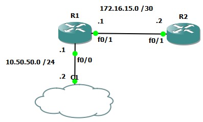
Once you have done the above, your GNS3 topology should look like this:
-
As you can see from the example topology above, the physical’s PC’s address is going to 10.50.50.2. To configure this, in Windows, navigate to the “Manage Network Connections” settings and locate your “MS Loopback Adapter”. Configure the adapter with the above mentioned IP address.
-
Your PC will now be connected to the virtual network. This can be confirmed by sending a couple of pings:
 ping 10.50.50.1

 Pinging 10.50.50.1 with 32 bytes of data:
 Reply from 10.50.50.1: bytes=32 time=63ms TTL=255
 Reply from 10.50.50.1: bytes=32 time=62ms TTL=255
 Reply from 10.50.50.1: bytes=32 time=32ms TTL=255
 Reply from 10.50.50.1: bytes=32 time=50ms TTL=255

 Ping statistics for 10.50.50.1:
  Packets: Sent = 4, Received = 4, Lost = 0 (0% loss),
 Approximate round trip times in milli-seconds:
  Minimum = 32ms, Maximum = 63ms, Average = 51ms
However, pings to all other virtual network subnets will not work at this stage. This is because your PC will be using the default route configured on your physical network card to try to access these networks. To fix this, continue on to Step 9.
-
What you’ll need to do now is install a route on your PC, telling it to route traffic destined to virtual networks through your loopback adapter.
For this example you’d need to issue the following command:
route add 172.16.15.0 mask 255.255.255.0 10.50.50.2Note: You will need to add a route for every subnet you are using in your virtual GNS3 network and point it out of your loopback interface.
Once you have done that, your data will be able to flow freely between the virtual network and your physical PC.
And that’s it! Your done!
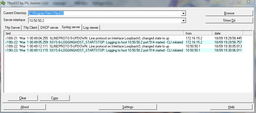
Here is an example of a Syslog server running on the physical PC. It is receiving log messages from both R1 and R2 (10.50.50.1 and 172.16.15.2 respectively):
UPDATE
Please see my new website for a step by step guide, including screenshots and network diagrams.
As always, if you have any questions or have a topic that you would like me to discuss, please feel free to post a comment at the bottom of this blog entry, e-mail at will@oznetnerd.com, or drop me a message on Reddit (OzNetNerd).
Note: The opinions expressed in this blog are my own and not those of my employer.

Leave a comment