
Note: This post carries on from Part 2.
Virtual Steelhead
Installation
Now that the vSwitches are set up, the next thing you will need to do is install the VSHs.
- Through the vSphere client, install the VSH by clicking on “File” > “Deploy OVF Template”.
- When asked for the name of the VM, type “VSH-A”.
-
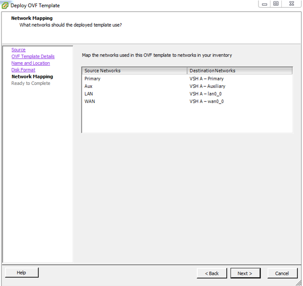
When configuring the NICs, match the “Source Networks” to their appropriate “Destination Networks”, as per the image below.
- Power on the VM and open a vSphere client console session to it.
- Log in to the appliance using “admin” and “password” as the credentials.
-
You will then be presented with the initial configuration wizard. See the responses to the wizard’s questions in the image below:

-
Press enter twice to save the configuration.
Note: You can now access VSH-A through your web browser by browsing to http://10.1.2.252 – and, once you’ve completed Step 8, you can access VSH-B by browsing to http://10.3.5.252
-
Repeat steps 1 through 7 but this time use VSH-B’s details while deploying the VM:
- Name the VM “VSH-B”
- Use the “VSH-B” destination networks
Also, use VSH-B’s details while completing the initial configuration wizard:
Step: Setting: Step 1: Hostname VSH-B Step 3: Primary IP address 10.3.5.252 Step 5: Default gateway 10.3.5.15 Step 14: In-Path IP 10.3.7.254 Step 16: In-Path Default gateway 10.3.7.14 Note: Refer to the “Final Diagram” diagram in Part 1 for more information about the interfaces and their IP addresses.
Note: If you make a mistake while completing the wizard, you can re-run it by issuing the following commands:
enable
configuration terminal
configuration jump-start
Licencing
Once you’ve completed the VSH installs and have logged in to them via a web browser, you will see an alert which states that optimisation is not properly licenced. To resolve this issue, complete the following steps on both VSHs:
- Obtain a couple of tokens from Riverbed.
- On your VSHs, navigate to the “Licenses” page and paste one of the tokens in to the “License Request Token” field, then click “Generate License Request Key”.
- The page will reload and you will be given a “license request key”. Copy and paste it in to Riverbed’s licences page.
- After completing the previous step, you will be presented with a list of licences. Click on the “View Keys - text” link which is located near the top of the page, then copy all of the licences which are at the bottom of the page.
- Go back to your VSH’s licences page and click the “Add a New License” button. Paste all of the licences in to the box and then click “Add”.
- You must now restart the Optimisation Service. You do this by navigating to “Configure” > ”Maintenance” > “Services”, and clicking the “Restart” button.
- Refresh the page and the licencing alert should no longer appear. The appliance’s status will also change from “Critical” to “Healthy”.
- Click the “Save” at the top of the page.
GNS3
To tie everything together, and to add routing to your lab topology, you’ll now need to set up GNS3.
VLAN Configuration
As mentioned earlier, you can configure SW1 and SW2 to allow multiple devices to connect to the VSH’s Primary, Auxiliary and lan0_0 subnets. To do this, use the following mappings:
|
SW1 |
|||
|
Switch Port #: |
VLAN: |
Connects to: |
Description: |
|
1 |
VLAN 2 |
VMnet1 (VSH-A Primary interface) |
VSH-A Primary Interface VLAN |
|
2 |
VLAN 2 |
R3, Fa0/0 |
|
|
3 |
VLAN 3 |
VMnet2 (VSH-A Auxiliary interface) |
VSH-A Auxiliary Interface VLAN |
|
4 |
VLAN 3 |
R3, Fa0/1 |
|
|
5 |
VLAN 4 |
VMnet3 (VSH-A lan0_0 interface) |
VSH-A lan0_0 Interface VLAN |
|
6 |
VLAN 4 |
R3, Fa1/0 |
|
|
SW2 |
|||
|
Switch Port #: |
VLAN: |
Connects to: |
Description: |
|
1 |
VLAN 5 |
VMnet5 (VSH-B Primary interface) |
VSH-B Primary Interface VLAN |
|
2 |
VLAN 5 |
R5, Fa0/0 |
|
|
3 |
VLAN 6 |
VMnet6 (VSH-B Auxiliary interface) |
VSH-B Auxiliary Interface VLAN |
|
4 |
VLAN 6 |
R5, Fa0/1 |
|
|
5 |
VLAN 7 |
VMnet7 (VSH-B lan0_0 interface) |
VSH-B lan0_0 Interface VLAN |
|
6 |
VLAN 7 |
R5, Fa1/0 |
|
However, before you can map the VSHs’ interfaces to GNS3 (the VMnet interfaces in the above tables), first you must use GNS3 “Cloud” nodes to represent the VSHs and attach the VMnet interfaces to them.
Note: You can use this method to connect any equipment (whether it be physical or virtual) to GNS3, not just Virtual Steelheads.
Cloud Nodes
When you want to connect GNS3 routers to equipment which resides outside of GNS3, you need to use Cloud nodes. These nodes allow you to bind both physical and virtual NICs to your GNS3 topology. You then connect these NICs to your equipment and you’ll then be able to pass traffic between GNS3 and your equipment.
You can then change the cloud’s icon to something that more closely relates to the equipment you’re using. In the case of the GNS3 topology discussed in this guide, the icons for VM-PC-1 and VM-PC-2 (the Windows XP VMs) were changed from clouds to servers, and the VSH’s icons were changed from clouds to firewalls (seeing as though there is no Steelhead” icon).
Note: The icons for PC-A-01, PC-A-02 and PC-B-01 (which are GNS3 routers, not clouds) were changed to PCs because they’re being used to perform similar jobs to the test PCs.
To connect the VSHs’ interfaces to GNS3, complete the following steps:
- Drag two GNS3 switches in to the topology pane and configure their interfaces and VLAN assignments in accordance with the information provided in the “VLAN Configuration” section above.
- Drag a Cloud node in to the topology pane.
- Change the icon to something other than a cloud. As mentioned above, I used a Firewall icon.
- Change the cloud’s name to VSH-A.
- Double click on the cloud. When the new window opens, click on the cloud’s name in the left pane.
-
From the “Generic Ethernet NIO” dropdown menu, select the VMnet1 interface and then click “Add”.
The below image shows VMNet1 being selected for the VSH-A node:

-
Using the table below, repeat Step 6 until all of the VSH-A VMnet interfaces have been added the cloud:
Cloud Node: VMnet: VSH-A VMnet1 VSH-A VMnet2 VSH-A VMnet3 VSH-A VMnet4 VSH-B VMnet5 VSH-B VMnet6 VSH-B VMnet7 VSH-B VMnet8 Important: The order in which you add each VMnet interface to the Cloud node is very important. This is because when you’re linking these interfaces to other interfaces in GNS3, the VMnet interfaces will be listed in the same order but won’t be shown in an understandable format. For example, when connecting VSH-A to SW1 you will be presented with a list similar to this:
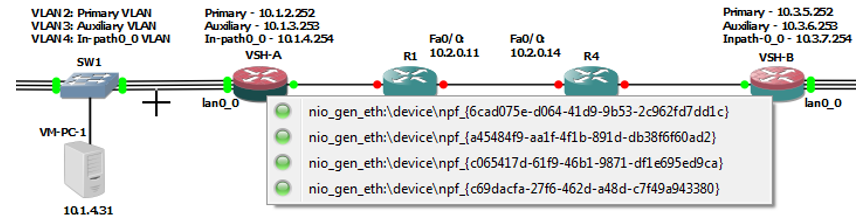
By adding the interfaces in the order which they appear in the table above, you will know that the first interface in the list is VMnet1, the second in the list is VMnet2, and so on. If you add them in a random order it will be difficult to decipher which is which.
- Repeat Steps 2 through 7 for VSH-B.
- Once all interfaces are mapped to their corresponding VSH icons, connect them to the destination ports as shown in the “VLAN Configuration” section above.
- Connect VMnet4 and VMnet8 to R1 and R4’s Fa0/1 interfaces respectively.
Router Configuration
To configure the routers, simply look at the “Final Diagram” in Part 1 and configure the interfaces accordingly, then use your favourite routing protocol(s) to enabling end to end connectivity.
Transfer Speeds
Any traffic that flows through a GNS3 router is slowed dramatically. Generally it is not possible to get throughput of more than 5MB/sec. This is why, as per the “Final Diagram” in Part 1, the two Windows XP VMs do not connect to the VSHs through a GNS3 router. If they did, you would not see any of the throughput improvements the VSHs provide.
Having said that though, it’s not all bad news. Because the two VSHs are separated by GNS3 routers the traffic that flows between the two “sites” is extremely slow. This results in the perfect testing environment to demonstrate the advantages of using features like SDR. (See the test results in Part 4 for more information).
If you’d like to connect your VSHs to real lab equipment and avoid the slow speeds GNS3 introduces, see the “Final Notes” section in Part 4.
As always, if you have any questions or have a topic that you would like me to discuss, please feel free to post a comment at the bottom of this blog entry, e-mail at will@oznetnerd.com, or drop me a message on Reddit (OzNetNerd).
Note: The opinions expressed in this blog are my own and not those of my employer.

Leave a comment