In my previous post I described how you can achieve 80Gb per blade with a UCS system. I went a little deeper than I had intended, so I thought it would be good to give readers another explanation from another blogger’s point of view.
How UCS achieves 80GbE of bandwidth per blade
With the launch of the third generation of Unified Fabric, Cisco’s UCS system has moved well ahead of the simple 2*10GbE interfaces that a single blade can have. It now delivers up to 80GbE to a single blade in a dual 40GbE way. How is that achieved? What are the options?
There are four main parts that you need to understand in order to answer the above question.
- Backplane
- IO Modules
- Blades, the M2 and M3
- Adapters
You will see in the following pictures and text an A-side and a B-side. The data plane is split into two completely separate fabrics (A and B). Each side consists of a Fabric Interconnect (UCS6100/6200) and an IO-Module (2100/2200). And each blade is connected to both the A and B sides of the fabric. This is a full active/active setup. The concept of active/standby does not exist within the Cisco UCS architecture.
Backplane
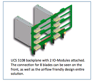
Since Cisco started shipping UCS in 2009, the Cisco 5108 chassis uses the same backplane. It is designed to connect 8 blades and 2 IO Modules. The backplane contains 64 10Gb-KR lanes, 32 from IOM-A and 32 from IOM-B.
All UCS Chassis sold to date have this backplane which provides a total of 8 10Gb-KR lanes going to each blade slot. This means every chassis sold so far is completely ready to deliver 80Gb of bandwidth to every blade slot.
IO-Modules
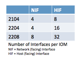
The IO Modules are an implementation of the Cisco Fabric Extender (FEX) architecture, where the IO-Module operates as a remote line card to the Fabric Interconnect. The IO-Module has network facing interfaces (NIF) which connect the IOM to the Fabric Interconnect, and host facing interfaces (HIF) which connect the IOM to the adapters on the blades. All interfaces are 10Gb DCE (Data Center Ethernet).
There are three different IOMs, each providing a different number of interfaces.
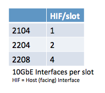
With 8 blade slots in the chassis, the table on the right shows the number of 10Gb interfaces that are delivered to a single blade slot.
Lets complete the picture and look at the total bandwidth going to each blade slot. Each chassis has the A-side and B-side IOM, and each IOM provides the number of interfaces listed in the above table. Because UCS only runs in active/active, that brings the total bandwidth to each blade slot to:
The Blades and Adapters
Hopefully by now you will have understood how the backplane delivers 8 10Gb-KR lanes to each blade slot and that the choice of IO Module determines how many of these are actually used. Now the blades themselves connect to the backplane via a connector that passes the 8 10Gb-KR lanes onto the motherboard.
Depending on the generation of blade (M2 and M3) these 8 10Gb-KR copper traces are distributed amongst the available adapters on the blade.
M2 blade
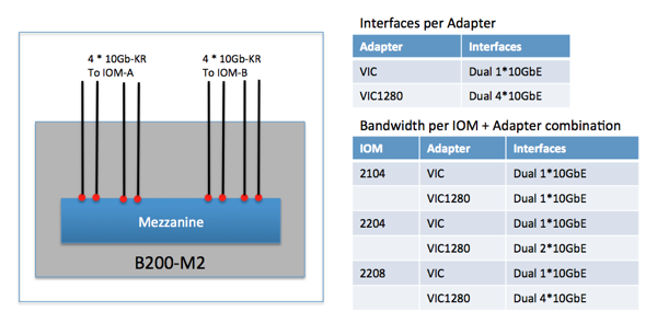
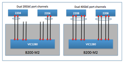
This is the easy one to explain because the M2 blades are designed with a single mezzanine adapter slot. That means all 8 10Gb-KR lanes go to this single adapter. Depending on the adapter that is selected to be placed in the mezzanine slot, the actual number of interfaces available will differ. Every adapter will have an dual interfaces connected to both IOM-A and IOM-B.
The adapter choice for the M2 blades is either a 2 or 8 interface adapter. Remember the backplane and IOM paragraph, the IOM choice also determines the number of active interfaces on the adapter as can be seen in the above picture and table.
The final piece to be aware of is the fully automatic port-channel creation between the VIC1280 and the 2204/2208. This creates a dual 20GbE or dual 40GbE port-channel with automatic flow distribution across the lanes in the port-channel.
M3 blade
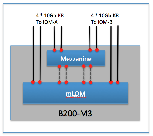
The M3 blades offer both an mLOM slot as well as an extra mezzanine adapter slot. It splits the 8 10Gb-KR lanes it receives from the backplane to both. This means customers can run a redundant pair of IO adapters on the M3 blade if they desire (some RfP’ explicitly ask for physically redundant IO adapters).
The M3 blade splits up the 8 10Gb-KR lanes by delivering 4 to the mLOM and the remaining 4 to the mezzanine slot. Of course these are connected evenly to the IOM-A and IOM-B side. There are also 4 lanes that run on the motherboard between the mezzanine and mLOM.
This means that the mLOM slot receives a total of 8 10Gb-KR lanes, 4 from the backplane and 4 from the mezzanine slot on the blade. This will become relevant when we discuss the Port-Extender options for the M3.
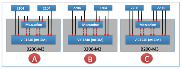
Now that it is clear how the 10Gb-KR lanes are distributed amongst the mLOM and Mezzanine on the blade, lets take a look at how they map to the three possible IO Modules. The mLOM today is always the VIC1240.
In picture A – with the 2104 as IO Module, it is clear that there is a single 10GbE-KR lane from each IOM that goes to the mLOM VIC1240. The mezzanine slot in this scenario cannot be used for IO functionality as there are no 10Gb-KR lanes that connect it to the IOM.
In picture B – with the 2204 as IO Module, there are two 10GbE-KR lanes from each IOM. The mLOM VIC1240 receives a single 10Gb-KR from each IOM. The second 10Gb-KR lane goes to the mezzanine slot. There are three adapter choices for the Mezzanine slot. It is my opinion that the “Port-Extender” will be the most popular choice for this configuration.
In picture C – with the 2208 as IO Module, there are four 10GbE-KR lanes from each IOM. The mLOM VIC1240 will received a dual 10Gb-KR from each IOM. The other two 10Gb-KR lanes go to the mezzanine slot. Again here are three adapter choices for the Mezzanine slot. It is my opinion that here also the “Port-Extender” will be the most popular choice for this configuration.
Since I think the Port-Extender will be the most popular mezzanine adapter – lets cover what it is. Simply put, it extends the four 10Gb-KR lanes from the backplane to the mLOM by using the “dotted gray” lanes in the above picture. Look at it as a pass-through module.
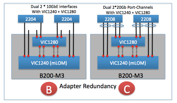
If we take both picture B and C and add a Port-Extender into it, lets see what we get. Remember that whenever possible, an automatic port-channel will be created as can be seen in the following picture.
Lets do the same but now use a VIC1280 as a completely separate IO adapter in the Mezzanine slot. This provides full adapter redundancy for the M3 blade for those customers that need that extra level of redundancy. The automatic port-channels are created from both the mLOM VIC1240 as well as the VIC1280 mezzanine adapter.
Summary
The UCS system can deliver up to 80GbE of bandwidth to each blade in a very effective way, without filling the chassis with a lot of expensive switches. Just two IO-Modules can deliver the 80GbE to each blade. That to my knowledge is a first in the blade-server market and shows the UCS architecture was designed to be flexible and cost effective.
Deep Dive & 160Gb per Blade
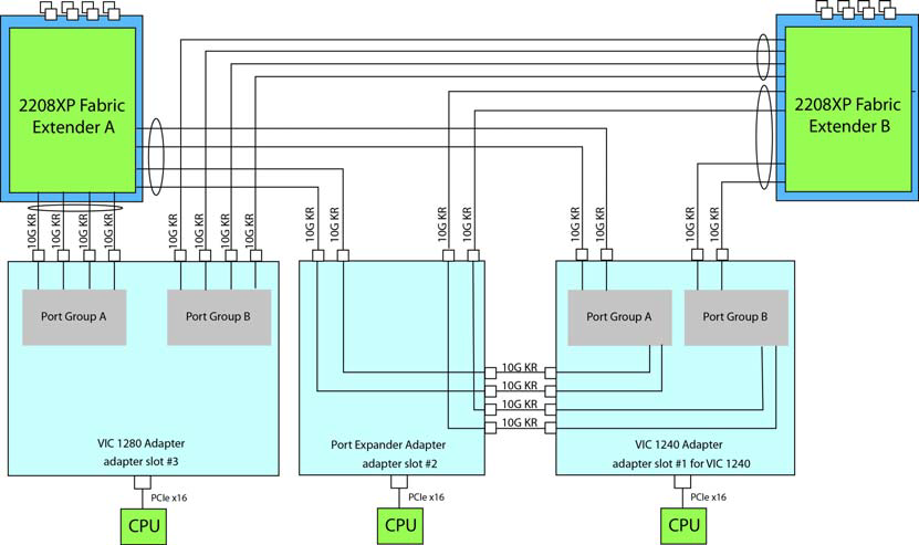
If you’d like to dive deeper into the connectivity between VICs and IOMs, and if you’d like to know how you can achieve 160Gb per blade, take a look at this post over at ecktech.me
The image below is a bit of a teaser. It shows how, by using a B420M3 blade with a VIC1240, port expander and a VIC1280, you can achieve 160Gb.
20Gb + 20Gb = 10Gb?
Finally, there’s one other post I highly recommend you read. It’s called “20Gb + 20Gb = 10Gb? UCS M3 Blade I/O Explained“ and can be found over at UCSguru.com. The post goes into detail about the issue I have mentioned a couple of times in this post, where choosing the wrong equipment results in lower than expected speeds.
Other Posts in this Series
See the Cisco UCS From the Ground Up – A Beginner’s Guide – Index post for links to all of the posts in this series.
As always, if you have any questions or have a topic that you would like me to discuss, please feel free to post a comment at the bottom of this blog entry, e-mail at will@oznetnerd.com, or drop me a message on Reddit (OzNetNerd).
Note: The opinions expressed in this blog are my own and not those of my employer.




Leave a comment