
To properly administer an EIGRP network an admin really should know how EIGRP calculates and chooses best paths. If you’ve read any CCNA or CCNP resource you’re probably thinking “that’s easy, EIGRP uses Bandwidth and Delay by default”. And you’re completely right. However, how do these two pieces of information actually influence the resulting metric?
Let’s take a look at what EIGRP devices (routers and switches) do with the bandwidth and delay values:
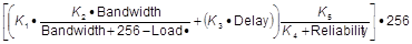
If you haven’t seen it before, it is the formula EIGRP devices use to calculate the metric of a route. If you’re not sure how to read this formula, don’t worry, I’ve got a shortcut :) But I’ll get to that in a moment.
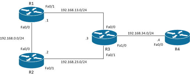
Throughout this post I will be referring to the path which traffic takes when going from R2 to the 192.168.34.0/24 network which resides on R3 and R4 as per this topology diagram:
The two things I would like to find out are:
- Which path does the traffic take? Does it go directly via R3, or does it go via R1 then R3?
- What can I do to make the metric through both paths exactly the same and therefore achieve load balance across them without using the “variance” command?
Question 1 Answered
Let’s first take a look at the EIGRP topology table on R2:
```R2#sh ip ei top all | s 192.168.34.0 P 192.168.34.0/24, 1 successors, FD is 284160, serno 53 via 192.168.23.3 (284160/28160), FastEthernet0/1 via 192.168.0.1 (309760/284160), FastEthernet0/0
Excellent, we've just found our answer. As highlighted above, the traffic is going via **R3** and **R3** only. This is because the path through **R3** has a lower Feasible Distance than the path through **R1**.

However, now I have a new question. How did EIGRP come up with the Feasible Distance of 284160? Well, we answered that above when we said "bandwidth and delay". But let's dive a bit deeper:

```R2#sh ip route 192.168.34.0
Routing entry for 192.168.34.0/24
  Known via "eigrp 1", distance 90, metric 284160, type internal
  Redistributing via eigrp 1
  Last update from 192.168.23.3 on FastEthernet0/1, 00:01:24 ago
  Routing Descriptor Blocks:
  * 192.168.23.3, from 192.168.23.3, 00:01:24 ago, via FastEthernet0/1
      Route metric is 284160, traffic share count is 1
      Total delay is **1100 microseconds**, minimum bandwidth is **10000** Kbit
      Reliability 255/255, minimum MTU 1500 bytes
      Loading 1/255, Hops 1
As per the output above we can see the cumulative delay between R2 and the 192.168.34.0/24 network. We can also see the minimum bandwidth along the path as well. Using these two pieces of information we’re able to manually calculate the Feasible Distance using the following “shortcut” formula I mentioned previously:
EIGRP Metric = 256*[(10000000/)+(/10)]
That’s much easier to work with than the official EIGRP formula, wouldn’t you say? :) Let’s do the calculations:
Minimum Bandwidth Calculation: 10000000/10000 = 1000
Total Delay Calculation: 1100/10 = 110
Add Results: 1000 + 110 = 1110
Multiply Results: 1110 * 256 = 284160
And there we have it, the formula works! Now before we jump into answering Question 2 let me first point out an issue that some people run into when using the “delay” command.
Microseconds & Tens of Microseconds
As we can see in the “show ip route” output above as well as the “show interface” output below, we’re given the delay in microseconds.
R2#sh int f0/1 | i DLY
MTU 1500 bytes, BW 10000 Kbit/sec, DLY **1000 usec**,
However, if we want to change the delay of an interface we must specify it in tens of microseconds.
switch(config-if)#delay ?
    Throughput delay (**tens of microseconds**)
In other words the “show interface” and “show ip route” output is 10 times that of the “delay” command. This means that if we want the “show interface” output to have a delay of 1000 microseconds, we need to issue the “delay 100” command. Another example would be if we were to use the “delay 5” command, it would result in the “show interface” output displaying a delay of 50 microseconds. Confusing, isn’t it?!
While we’re on the topic, 1 is the lowest figure we can use with the “delay” command. This means that the smallest delay we can configure on an interface is 10 microseconds. Using the “shortcut” formula above let’s see how 10 microseconds affects the EIGRP metric calculation. In order to do this let’s first recap on which figures we need.
As per the “show ip route” output above we see that the total delay is 1100 microseconds. This is made up of 1000 microseconds on R2’s Fa0/1 interface and 100 microseconds on R3’s Fa1/0 interface. Putting it diagrammatically, it looks like this:
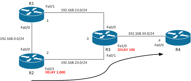
Therefore to increase the total delay by 10 microseconds we need to issue the “delay 101” command (1010 microseconds) on R2’s Fa0/1 interface. Alternatively, we could issue the “delay 11” command (110 microseconds) on R3’s Fa1/0 interface. Doing either of these two things will result in the total delay being 1110 microseconds as opposed to the 1100 microseconds that it was previously.
Now that we’ve got that out of the way, let’s run the figures through the “shortcut” formula:
Minimum Bandwidth Calculation: 10000000/10000 = 1000
Total Delay Calculation: 1110/10 = 111
Add Results: 1000 + 111 = 1111
Multiply Results: 1111 * 256 = 284416
By subtracting the metric in our newly calculated metric from our previously calculated metric, we find how adding 10 microseconds of delay affects the metric calculation:
284416 - 284160 = 256
In other words by increasing the delay by 10 microseconds, we increase the resulting metric by 256. If we increase it by 20 microseconds, it will add 512 to the metric. If we increase it by 100 microseconds, it will add 25,600 to the metric… I’m sure you get the idea.
Question 2 Answered
Now that we know how changing the delay affects the metric calculation, making the paths through R1 and R3 have equal metrics will be easy.
Recall that in the very first output above we saw that the path via R1 had Feasible Distance of 309760 and the path via R3 had a Feasible Distance of 284160 . To find out the difference between the two let’s subtract the former from the latter:
309760 - 284160 = 25600
Therefore in order for us to achieve equal cost load balancing, we’ll need to add 25600 to the metric for the path via R3. Doing so will result in it having the exact same metric as the path via R1.
Because there is no command which allows us to simply add 25600 to the metric we’ll need to use the “delay” command instead. This is fine because we’ve already done the hard work above. We found that each time we increase an interface’s delay by 1, we add 256 to the metric. Therefore all we need to do is another simple calculation:
25600/256 = 100
This means all we need to do now is add an additional 100 tens of microseconds (also known as 1,000 microseconds) to the path via R3. As mentioned above and pasted below for convenience, R2’s Fa0/1 interface already as a delay of 1000 microseconds (also known as 100 tens of microseconds).
R2#sh int f0/1 | i DLY
MTU 1500 bytes, BW 10000 Kbit/sec, DLY **1000 usec**,
Therefore, to add the additional 100 tens of microseconds we’ll need to use the “delay 200” command (100 to cover the existing 1000 microseconds of delay, and then the another 100 to cover the additional 1000 microseconds of delay that we’d like to add). As shown below, this will result in the interface’s delay being changed to 2000 microseconds:
R2(config-if)#int f0/1
R2(config-if)#del 200
R2(config-if)#do sh int f0/1 | i DLY
  MTU 1500 bytes, BW 10000 Kbit/sec, DLY **2000** usec,
Now if our calculations above were correct we should see that the paths via R1 and R3 have the exact same Feasible Distance, which therefore results in automatic equal cost load balancing:
R2(config-if)#do sh ip ei top all | s 192.168.34.0
P 192.168.34.0/24, **2 successors**, FD is 258816, serno 71
        via 192.168.23.3 (**309760**/28160), FastEthernet0/1
        via 192.168.0.1 (**309760**/284160), FastEthernet0/0

R2(config-if)#do sh ip route 192.168.34.0
Routing entry for 192.168.34.0/24
  Known via "eigrp 1", distance 90, metric 309760, type internal
  Redistributing via eigrp 1
  Last update from 192.168.0.1 on FastEthernet0/0, 00:11:00 ago
  Routing Descriptor Blocks:
  * 192.168.23.3, from 192.168.23.3, 00:11:00 ago, via FastEthernet0/1
      Route metric is **309760**, traffic share count is 1
      Total delay is 2100 microseconds, minimum bandwidth is 10000 Kbit
      Reliability 255/255, minimum MTU 1500 bytes
      Loading 1/255, **Hops 1**
    192.168.0.1, from 192.168.0.1, 00:11:00 ago, via FastEthernet0/0
      Route metric is **309760**, traffic share count is 1
      Total delay is 2100 microseconds, minimum bandwidth is 10000 Kbit
      Reliability 255/255, minimum MTU 1500 bytes
      Loading 1/255, **Hops 2**
Success! We did it! The “2 Successors” tells us that both paths have been added to the routing table, as does the two entries in the “show ip route” output.
Final Thoughts
I know this was a fairly long post so I hope I didn’t lose you along the way. If I did, please feel free to leave a comment or drop me an e-mail and I’d be happy to further explain anything you might not quite understand.
If you were able to follow until the end the great news. You now posses the knowledge required to finely manipulate EIGRP metric calculations and path selections. Congratulations!
As always, if you have any questions or have a topic that you would like me to discuss, please feel free to post a comment at the bottom of this blog entry, e-mail at will@oznetnerd.com, or drop me a message on Reddit (OzNetNerd).
Note: The opinions expressed in this blog are my own and not those of my employer.