
A little while back I began looking into WAN optimisation, and in particular, Riverbed’s Steelheads. I really enjoyed all that I was reading so decided it was time to fire up a few Virtual Steelheads in my lab. As was the case in my Connecting the NetApp Simulator to your Virtual and Physical Labs and Trunking VLANs between the NetApp Simulator and GNS3 posts, GNS3 again plays an instrumental part in getting this lab up and running.
The reason why I have called this a “Self-Contained” lab is because, as you will soon see, it demonstrates you how can replicate a real-life setup using a single PC or laptop with the following applications:
- GNS3 (installed on your PC)
- VMWare Workstation (installed on your PC)
- Two Windows VMs (running in Workstation)
- Two ESXi hosts (running in Workstation)
- Two Virtual Steelheads (one installed per ESXi host)
(With all of this virtualisation inside of virtualisation taking place, I can’t help but think about the movie Inception) :)
Background
Before jumping into the configuration details, I’ll run through a few things which you will need to know in order to complete the setup.
What You’ll Need
To create this lab you’ll need a couple of things, as listed below. (I have put the equipment/versions that I used in brackets):
- A reasonably powerful machine (i5-3230M 2.60GHz CPU and 8gb of RAM)
- VMware Workstation (Version 9)
- ESXi (Version 5.5)
- GNS3
- IOS for GNS3 (c3745-adventerprisek9-mz.124-15.T14.bin)
- Operating system used for lab PCs (Windows XP)
- x2 Virtual Steelhead Appliance trials
Once the lab is completed your traffic flow will look like this:
XP (Workstation) > VSH (ESXi) > Router (GNS3) > Router (GNS3) > VSH (ESXi) > XP (Workstation)
Note: This guide is quite long and involves a lot of interfaces and IP addresses. I recommend looking at the “Final Diagram” image below intermittently so that you can see which point of the network I’m referring to when I’m talking about interfaces and/or IPs.
Final Diagram
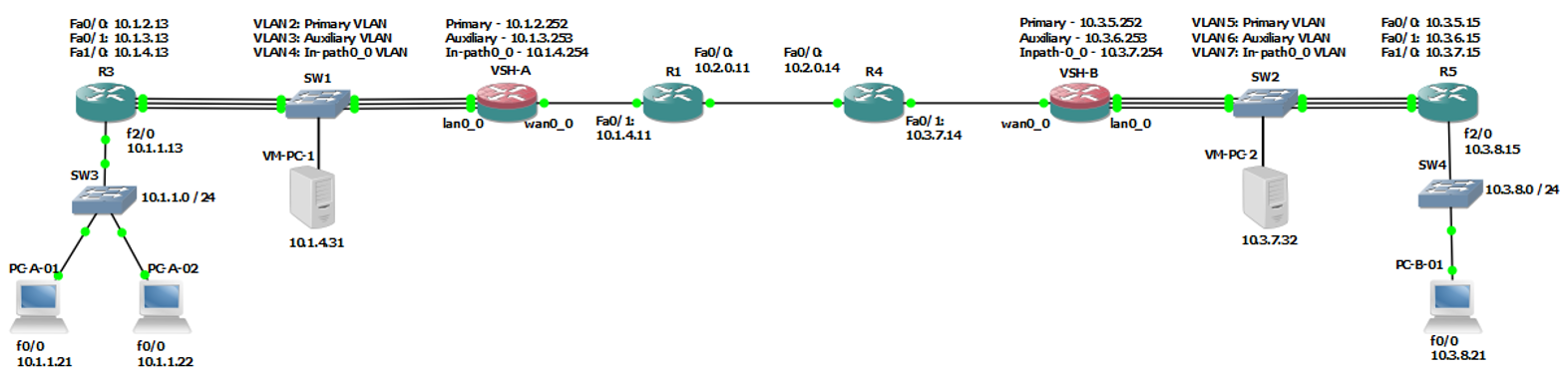
Virtual Steelhead (VSH) Interfaces
The VSHs have the following interfaces -
- Primary - Used for out of band management and for out-of-path configurations
- Auxiliary - Management port
- In-path0_0 - A virtual interface that is made up of a physical WAN and a physical LAN interface. These interfaces are bridged and are therefore part of the same layer 2 domain
- lan0_0 – Connects to the LAN side of the network (e.g switch)
- wan0_0 – Connects to the WAN side of the network (e.g border router)
The Primary and Auxiliary interfaces cannot be put on the same subnet, and in the setup described later, the in-path0_0 is on a different subnet too.
Important: It is important to remember that the in-path0_0 interface is virtual because, as you will see later on, the in-path0_0 interface has no VMware NICs mapped to it while all other interfaces do. It is also important to remember that the lan0_0 and wan0_0 interfaces are bridged. This is because they are the only two interfaces which will be on the same subnet, and because they’re used to intercept traffic which is not destined for the VSHs, they are the only interfaces which need to run in promiscuous mode.
Note: Although it is not a requirement to connect both the Primary and Auxiliary interfaces, this guide does. This was done so that you’ve got the option of using either of them, whichever best suits your topology’s needs.
Topology Diagram
To begin with, it is a good idea to create a topology diagram. Having a diagram will avoid a lot of headaches later on down the track when it comes to IP addressing, interface numbers and traffic flow.
The following topology was used to write this guide:
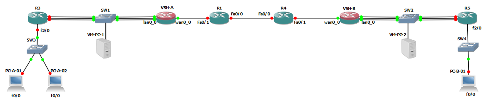
In this topology, the nodes were configured like so:
- PC-A-01, PC-A-02 and PC-B-01 are GNS3 routers with their icons changed to PCs. This was done because they are used to act as hosts on subnets which differ to the ones that the VSHs are on.
- VM-PC-1 and VM-PC-2 are Windows XP VMs. They are on the same subnet as the VSHs.
- There are three links between the VSHs and their respective neighbouring routers. These links are for the VSH’s Primary, Auxiliary and lan0_0 interfaces. (You wouldn’t see these interfaces connected in this way when looking at a real deployment. It was done this way in the lab so that all of the interfaces could be used without having to overcomplicate the topology).
Note: As per the interface numbering in the diagram above, it is good to be consistent. For example:
- PC-A-01, PC-A-02 and PC-B-01 use their fa0/0 interface to connect to their upstream switch
- R3 and R5 use their fa2/0 interface to connect to their downstream switch
- R1 and R4 use their Fa0/1 interface to connect to their Riverbed’s wan0_0 interface
- R1 and R4 use Fa0/0 as their WAN interface
IP Addressing & VLANs
Addressing
The next step is to come up with an IP addressing plan. Like with the interface numbering seen above, it’s a good idea to be consistent. Doing so can make your life a lot easier as your topology begins to grow.
For example, if you break up the topology into three segments, it would look like this:
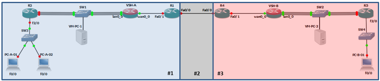
By putting each segment in a different network in the second octet you’ll have a manageable IP scheme. For example:
- Segment 1 = 10.1.x.0
- Segment 2 = 10.2.x.0
- Segment 3 = 10.3.x.0
To get even more granular, you can split the segments down further and use the third octet to represent each sub-segment:
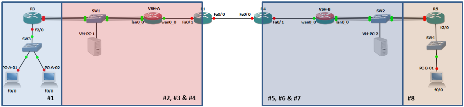
Note: Sub-segments 2, 3 and 4 as well as 5, 6 and 7 represent the subnets for the VSH’s Primary, Auxiliary and in-path0_0 interfaces.
Note: There is no need to split the Segment 2 (the WAN connection) any further.
This would result in the following IP addressing scheme:
- Segment 1:
- Sub-segment 1 = 10.1.1.0/24 (Segment 1 LAN network)
- Sub-segment 2 = 10.1.2.0/24 (VSH-A Primary network)
- Sub-segment 3 = 10.1.3.0/24 (VSH-A Auxiliary network)
- Sub-segment 4 = 10.1.4.0/24 (VSH-A in-path0_0 network)
- Segment 3:
- Sub-segment 5 = 10.3.5.0/24 (VSH-B Primary network)
- Sub-segment 6 = 10.3.6.0/24 (VSH-B Auxiliary network)
- Sub-segment 7 = 10.3.7.0/24 (VSH-B in-path0_0 network)
- Sub-segment 8 = 10.3.8.0/24 (Segment 2 LAN network)
Finally, when assigning host addresses, it is a good idea to match the last octet with the device’s hostname. For example:
- Routers = Hostname + 10
- Routers acting as PCs = Hostname + 20
- Windows XP VMs = Hostname + 30
Using Segment 1 (which consists of sub-segments 1 through 4) as an example, the IP addressing looks like this:
-
R1: 10.1.4.11 /24 (VSH-A in-path0_0 network)
- VSH-A Primary: 10.1.2.252 /24
- VSH-A Auxiliary: 10.1.3.253 /24
-
VSH-A in-path0_0: 10.1.4.254 /24
- R3: 10.1.2.13 /24 (VSH-A Primary network)
- R3:10.1.3.13 /24 (VSH-A Auxiliary network)
- R3:10.1.4.13 /24 (VSH-A in-path0_0 network)
-
R3: 10.1.1.13 /24 (Segment 1 LAN network)
- PC-A-01: 10.1.1.21 /24 (Segment 1 LAN network)
-
PC-A-02: 10.1.1.22 /24 (Segment 1 LAN network)
- VM-PC-1: 10.1.4.31 /24 (VSH-A in-path0_0 network)
Note: Some interfaces like the VSH’s Primary, Auxiliary and in-path0_0 aren’t numbered, so you can choose any you like. I chose the last three useable host addresses of a /24 subnet.
Finally, there is one other network which you need to set up, and that is the ESXi Host management address. This IP is used to administer the ESXi server VM. To keep its management IP address from conflicting with the IP plan outlined above, use 10.0.0.251/24.
See Part 2 to continue.
As always, if you have any questions or have a topic that you would like me to discuss, please feel free to post a comment at the bottom of this blog entry, e-mail at will@oznetnerd.com, or drop me a message on Reddit (OzNetNerd).
Note: The opinions expressed in this blog are my own and not those of my employer.

Leave a comment