
In my previous post Connecting the NetApp Simulator to your Virtual and Physical Labs, I explained the steps you need to follow in order to connect the NetApp simulator to GNS3. By doing this you’re able to connect the simulator to Cisco routers, Virtual Steelheads, ASA firewalls, F5 load balancers… to put it simply, just about any physical or virtual piece of equipment you can think of! This entry builds on that post and demonstrates how, with just a few extra steps, you’re able trunk VLANs between the simulator and GNS3.
To demonstrate its capabilities, I’ll explain three different methods GNS3 is able to handle the VLANs which are passed to it by the simulator. (Note that additional methods become available when you integrating other appliances into GNS3. For example, you could have the simulator hand off the VLANs to a Palo Alto firewall).
Creating VLANs & LIFs on the Simulator
Let’s begin by configuring the simulator side. We’ll need to create the VLANs and LIFs which we plan to make accessible to the device(s) in GNS3. For this example I’ll configure them in the following way:
- e0d-20 = 10.0.20.9 /24
- e0d-30 = 10.0.30.9 /24
- e0d-40 = 10.0.40.9 /24
To do this, we use the following commands:
cdot-clust::> network port vlan create -node cdot-clust-01 -vlan-name e0d-20
cdot-clust::> network port vlan create -node cdot-clust-01 -vlan-name e0d-30
cdot-clust::> network port vlan create -node cdot-clust-01 -vlan-name e0d-40
To view the changes, issue the following command:
cdot-clust::> network port show -node cdot-clust-01
 Auto-Negot  Duplex     Speed (Mbps)
 Node   Port   Role         Link   MTU Admin/Oper  Admin/Oper Admin/Oper
 ------ ------ ------------ ---- ----- ----------- ---------- ------------
 cdot-clust-01
 e0a    cluster      up    1500  true/true  full/full   auto/1000
 e0b    cluster      up    1500  true/true  full/full   auto/1000
 e0c    data         up    1500  true/true  full/full   auto/1000
 e0d    data         up    1500  true/true  full/full   auto/1000
 e0d-20 data         up    1500  true/true  full/full   auto/1000
 e0d-30 data         up    1500  true/true  full/full   auto/1000
 e0d-40 data         up    1500  true/true  full/full   auto/1000

7 entries were displayed.
Next, we need to configure the LIFs:
dot-clust::> network interface create -vserver Tenant1 -role data -lif iscsi20 -home-node cdot-clust-01 -home-port e0d-20 -address 10.0.20.9 -netmask-length 24
cdot-clust::> network interface create -vserver Tenant1 -role data -lif iscsi30 -home-node cdot-clust-01 -home-port e0d-30 -address 10.0.30.9 -netmask-length 24
cdot-clust::> network interface create -vserver Tenant1 -role data -lif cifs40 -home-node cdot-clust-01 -home-port e0d-40 -address 10.0.40.9 -netmask-length 24
To view the changes, we use the following command:
cdot-clust::> netw interface show -vserver Tenant1
 (network interface show)
 Logical    Status     Network            Current       Current Is
 Vserver     Interface  Admin/Oper Address/Mask       Node          Port    Home
 ----------- ---------- ---------- ------------------ ------------- ------- ----
 Tenant1
 cifs40       up/up    10.0.40.9/24       cdot-clust-01 e0d-40  true
 iscsi20      up/up    10.0.20.9/24       cdot-clust-01 e0d-20  true
 iscsi30      up/up    10.0.30.9/24       cdot-clust-01 e0d-30  true

 3 entries were displayed.
VMware Workstation Configuration
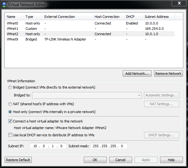
As covered in my previous post, in order for us to be able to connect the simulator to GNS3, we must first enable the “Connect a host virtual adapter to this network” option on the VMnet interface which is mapped to the simulator e0d interface. In this case it is VMnet2.
In regards to the screenshot below, note the following:
- It doesn’t matter what the “Subnet Address” is set to. It does not interfere with the three subnets we’ve configured above.
- Unlike the previous post, the “Use local DHCP service to distribute IP address to VMs” option is not selected.
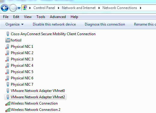
Also note that we now have two “VMware Network Adapter” interfaces:
GNS3 Topologies
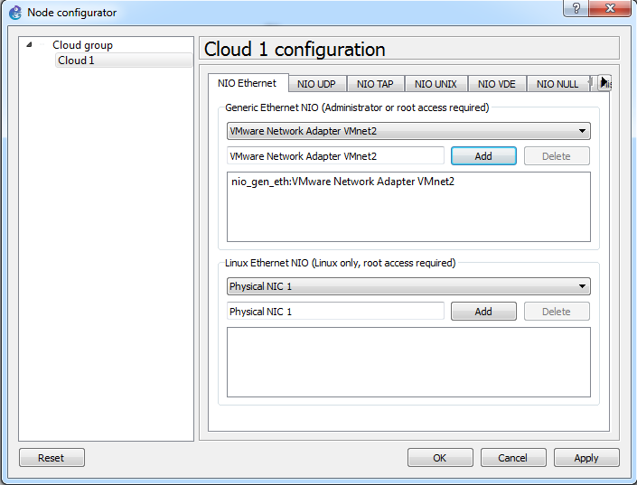
As mentioned above, I’ll be demonstrating three ways in which you can pass VLANs between the simulator and GNS3. In all three examples, the cloud is configured like so:
GNS3 Option #1 - Router
This option utilises a single router with multiple sub interfaces:
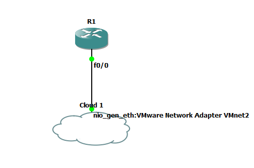
To enable this topology to work, the router’s Fa0/0 interface needs to be configured in the following way:
- Fa0/0.20 - VLAN 20
- Fa0/0.30 - VLAN 30
- Fa0/0.40 - VLAN 40
The configuration required to achieve this is as follows:
R1(config)#interface FastEthernet0/0
R1(config-if)#no shut

R1(config-if)#interface FastEthernet0/0.20
R1(config-subif)#encapsulation dot1Q 20
R1(config-subif)#ip address 10.0.20.1 255.255.255.0

R1(config-subif)#interface FastEthernet0/0.30
R1(config-subif)#encapsulation dot1Q 30
R1(config-subif)#ip address 10.0.30.1 255.255.255.0

R1(config-subif)#interface FastEthernet0/0.40
R1(config-subif)# encapsulation dot1Q 40
R1(config-subif)# ip address 10.0.40.1 255.255.255.0
Now let’s perform some ping tests:
R1(config-subif)#do ping 10.0.20.9

Type escape sequence to abort.
 Sending 5, 100-byte ICMP Echos to 10.0.20.9, timeout is 2 seconds:
 !!!!!
 Success rate is 100 percent (5/5), round-trip min/avg/max = 4/20/52 ms

R1(config-subif)#do ping 10.0.30.9

Type escape sequence to abort.
 Sending 5, 100-byte ICMP Echos to 10.0.30.9, timeout is 2 seconds:
 !!!!!
 Success rate is 100 percent (5/5), round-trip min/avg/max = 8/14/28 ms

R1(config-subif)#do ping 10.0.40.9

Type escape sequence to abort.
Sending 5, 100-byte ICMP Echos to 10.0.40.9, timeout is 2 seconds:
!!!!!
Success rate is 100 percent (5/5), round-trip min/avg/max = 8/16/32 ms
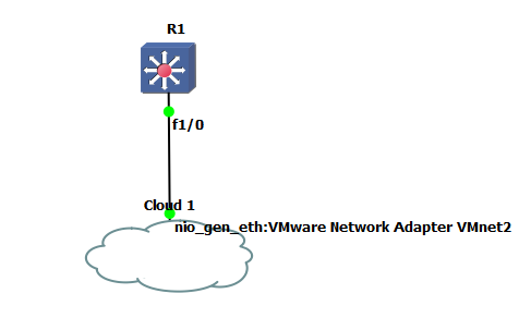
GNS3 Option #2 - Router with Switch Module
This option requires a switch module to be installed inside of the router:
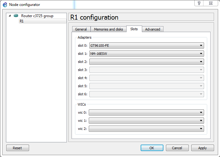
Note that although I’ve changed the router’s icon to a multilayer switch, it is exactly the same router as the one used in Option #1:
As we’re now dealing with a Layer 2 interface (as opposed to a Layer 3 interface as was the case with Option #1), the configuration is quite different:
R1(config)#vlan 20
R1(config-vlan)#vlan 30
R1(config-vlan)#vlan 40
R1(config-vlan)#int vlan 20
R1(config-if)#ip add 10.0.20.1 255.255.255.0

R1(config-if)#int vlan 30
R1(config-if)#ip add 10.0.30.1 255.255.255.0

R1(config-if)#int vlan 40
R1(config-if)#ip add 10.0.40.1 255.255.255.0

R1(config-if)#int fa1/0
R1(config-if)#swi mo tru
Now let’s perform some ping tests:
R1(config-if)#do ping 10.0.20.9

Type escape sequence to abort.
Sending 5, 100-byte ICMP Echos to 10.0.20.9, timeout is 2 seconds:
!!!!!
Success rate is 100 percent (5/5), round-trip min/avg/max = 1/12/24 ms

R1(config-if)#do ping 10.0.30.9

Type escape sequence to abort.
Sending 5, 100-byte ICMP Echos to 10.0.30.9, timeout is 2 seconds:
!!!!!
Success rate is 100 percent (5/5), round-trip min/avg/max = 8/13/20 ms

R1(config-if)#do ping 10.0.40.9

Type escape sequence to abort.
Sending 5, 100-byte ICMP Echos to 10.0.40.9, timeout is 2 seconds:
!!!!!
Success rate is 100 percent (5/5), round-trip min/avg/max = 8/16/28 ms
GNS3 Option #3 - Switch Multiple Routers
This option utilises GNS3’s switch to terminate the VLANs:
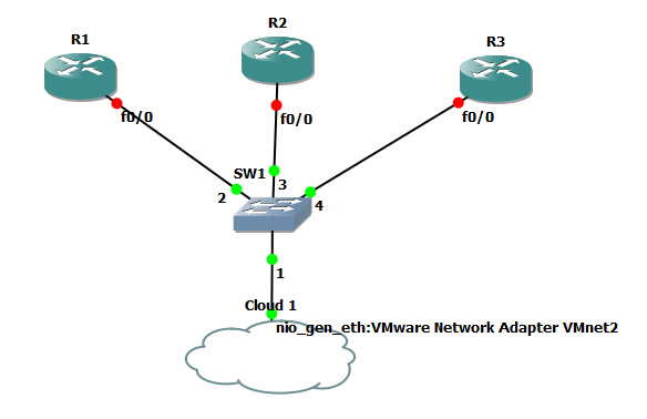
To enable this topology to work, the switch’s interfaces need to be configured in the following way:
- Port 1 - dot1q
- Port 2 - VLAN 20
- Port 3 - VLAN 30
- Port 4 - VLAN 40
This is what it looks like in GNS3’s node configurator:
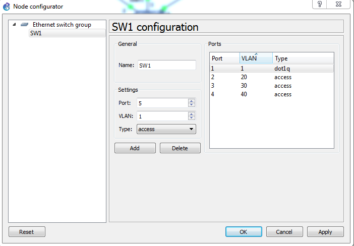
As the switch is handling the 802.1q packets, all we need to do is configure each router with an IP address on the corresponding subnet:
R1:
R1(config)#int f0/0
R1(config-if)#no shut
R1(config-if)#ip add 10.0.20.1 255.255.255.0
R1(config-if)#do ping 10.0.20.9

Type escape sequence to abort.
Sending 5, 100-byte ICMP Echos to 10.0.20.9, timeout is 2 seconds:
!!!!!
Success rate is 100 percent (5/5), round-trip min/avg/max = 8/19/48 ms
R2:
R2(config)#int f0/0
R2(config-if)#no shut
R2(config-if)#ip add 10.0.30.1 2
R2(config-if)#do ping 10.0.30.9

Type escape sequence to abort.
Sending 5, 100-byte ICMP Echos to 10.0.30.9, timeout is 2 seconds:
!!!!!
Success rate is 100 percent (5/5), round-trip min/avg/max = 8/20/40 ms
R3:
R3(config)#int f0/0
R3(config-if)#no shut
R3(config-if)#ip add 10.0.40.1 255.255.255.0
R3(config-if)#do ping 10.0.40.9

Type escape sequence to abort.
Sending 5, 100-byte ICMP Echos to 10.0.40.9, timeout is 2 seconds:
!!!!!
Success rate is 100 percent (5/5), round-trip min/avg/max = 4/16/44 ms
As always, if you have any questions or have a topic that you would like me to discuss, please feel free to post a comment at the bottom of this blog entry, e-mail at will@oznetnerd.com, or drop me a message on Reddit (OzNetNerd).
Note: The opinions expressed in this blog are my own and not those of my employer.